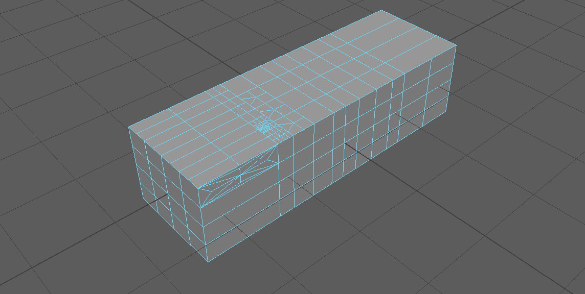
This post is a collection of related topics on polygon selection from the AUTODESK MAYA HELP . Click on the links below to read the access the full Help content on Autodesk website.
Connect
Interactively connect polygon components by inserting an edge between them.
- Mesh Tools > Connect
or
Click on “Connect” in Modeling Toolkit window.- Select a single vertex, edge, or face in your scene, and then Shift-select other components.
- Comd+Shift+RMB – to select one of options.
- MM-drag – to change the value.
Connect Tool options
Slide – Specifies where the edge is inserted on the mesh. When Slide is set to 0.50 (default), edges are inserted in the middle of a face.
Segments – Specifies the number of connected segments that are inserted into the mesh. The default is 1.
Pinch – Specifies the distance between the outer edge(s) and the connected segment(s).
Connect
Connecting multiple vertices and edges
- Shift-select vertices and edges.
- Edit Mesh > Connect
Poke
Split a face so that a vertex is added at its center
- Select one or more face.
- Edit Mesh > Poke
Divide faces
Divide faces into triangles or quadrangles
- Select the faces.
- Edit Mesh > Add Divisions
or
Click “Add Devisions” in the Modeling Toolkit.
Note!
- Exponentially subdivides the face or edge recursively. The Linearly setting subdivides the face into an absolute number of segments. In addition, with the Linearly setting, you can specify subdivisions in U and V.
- The Exponentially controls let you specify the Mode to be either triangles or quadrangles.
- You cannot use the Add Divisions feature on faces that contain holes. Also, you cannot subdivide concave faces unless the center point is inside the face.
- To subdivide a concave face into convex parts, use the Multi-Cut Tool or Mesh > Triangulate. To remove holes use Triangulate.
Subdivide faces by painting
- In the Toolbox, select the Paint Selection Tool.
- Turn off Add to Current Selection.In the Stroke section.
- Type the following in After Stroke Cmd: polySubdivideFacet -dv 1 -m 0 -ch 1
- Paint the faces you want to subdivide.
https://vimeo.com/159298052
Insert an edge loop
Splitting the polygon faces associated with the selected edge ring.
Four ways of adding edge loops:
Insert Edge Loop Tool
Mesh Tools > Insert Edge Loop Tool
Comd+Shift+RMB – To get the options.
TIP!
- Turning Auto complete off is useful when you want to insert edges on a partial edge ring or a multidirectional edge ring path.
- When Number of loops is set to 1, a single edge loop is inserted at the halfway point between the edges.
- Click here for additional attributes on the polySplitRing node.
https://vimeo.com/159298064
Mesh Tools > Offset Edge Loop
Comd+Shift+RMB – To get the options
https://vimeo.com/159298063
Quad Draw Tool
- Mesh Tools > Quad Draw
or
Click the ” Quad Draw” in the Modeling Toolkit.- Comd+Shift+RMB – To get the options
Auto-weld – to merge close vertices together.
- Shift+drag – Relax verices
- Ctrl+click – Insert an edge loop
- Ctrl+MMB -Insert an edge loop to center
- Ctrl+Shift+click – delete components
- Hold down Tab and draw quad strip
- Hold down Tab and drag an edge to extend
- Tab+Shift – To extend an edge loop
https://vimeo.com/159298066
Multi-Cut Tool
Slice a mesh with the Multi-Cut Tool
- Tools > Multi-Cut
or
Select the Multi-Cut Tool from the Modeling Toolkit window- To edit your cut:
- Press Backspace to remove points.
- Hold Shift to snap points along edges. Use the Snap % field in the Multi-Cut Options to adjust the snap interval.
- Drag to reposition cut points anywhere on your mesh.
- MM-drag – To reposition the first cut point to another position.
- MM-drag anywhere on the mesh to tweak the last cut point.
- Ctrl-drag or Ctrl + Shift-drag your cursor across the mesh to add an edge loop.
- To make a 90 degree angle cut, hold Ctrl + Shift and move your cursor close to your last cut point.
- Hold Ctrl + Shift and move your cursor over an existing edge to find other 90 degree angles.
- Z / Shift+Z – Undo / Redo
